What is Heathcote Slip?
By Sara Worley on 07/10/23
Heathcote slip is a phenomenon that is present in all spherical roller bearings. It is a geometrical constraint caused by the difference in radii between the roller and raceway.
The red dots on the figure below represent the areas of true rolling, denoted by R1 and R2. At these true rolling points as seen in Figure 1, there is no micro-differential slip or sliding effect occurring.

Figure 1: Bearing rolling elements showing Heathcote slip
This means that the other areas of the roller are rotating at different speeds. These areas which are shown in the above picture in blue, must be sliding/slipping while rotating. This differential slip that is occurring is the definition of Heathcote slip.
While Heathcote slip is present in all spherical roller bearings, not all bearings are seeing surface wear due to this. This is because, like peeling damage, these effects will become a problem as metal-to-metal contact occurs due to a poor lubrication environment.
Because main bearings are in a slow speed and poor lubrication environment, two different forms of wear will occur, which are adhesive and abrasive wear.
Adhesive Wear
This form of wear is synonymous with peeling damage and the micro-welding effect that occurs between the two metal surfaces as shown in Graphic 1. This form of damage is very common in main bearings and will eventually lead to internal bearing debris causing abrasive wear to occur as well.

Graphic 1: Peeling damage
Abrasive Wear
Heathcote slip is an example of abrasive wear caused by the slipping occurring between the roller and raceway combined with insufficient lubrication. Like adhesive wear, forms of abrasive wear will start due to the grease being unable to stop the roller surfaces from coming in contact with the raceway. Rather than a micro-welding effect occurring like with adhesive wear, the friction between the two surfaces will cause wear bands to form. This form of abrasive wear is also called 2-body wear. As internal bearing debris is created, 3-body wear will form as the roller continues to slide on the raceway.
As seen by the blue arrows in the below picture, the surface of the roller between the points of true rolling is slipping in the opposite direction of the outer areas of true rolling as seen in Figure 2. Because the area between true rolling has a higher surface velocity due to the curvature of the rolling element, it will also have a larger sliding force.
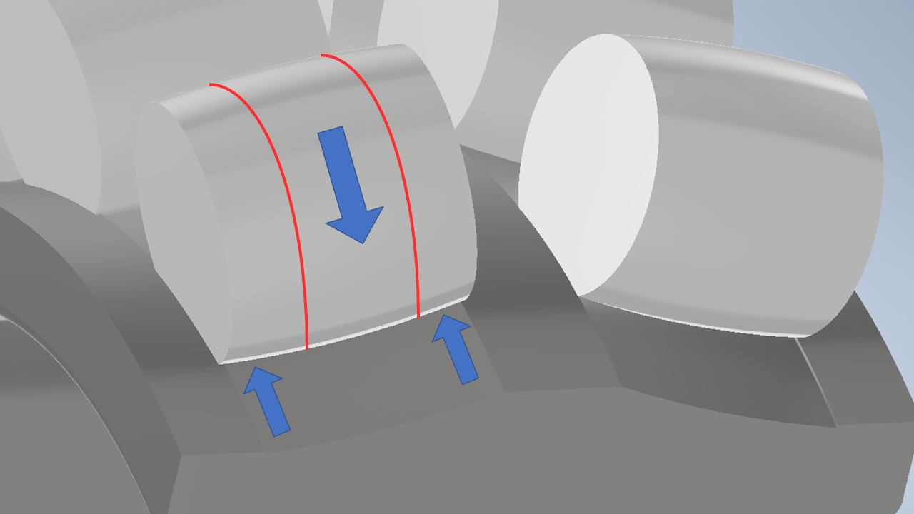
Figure 2: Demonstration of opposing sliding forces between the roller and raceway
This area of higher velocity and sliding will be where the abrasive wear starts during lubrication failure. This area will commonly see heavier adhesive wear as well. Eventually, at later stages of wear both the areas outside and inside of the true rolling points will see equal wear.
Heathcote slip also effects the formation of shape wear, a specific form of wear that occurs when the bearing is in the loading range of approximately 10-20% of its basic static load rating, defined as C0r.

Figure 3: Lines on bearing inner race representing two-peak wear on the raceway
Shape wear can also be referred to as two-peak wear. The green lines in Figure 3 represent the wave-like pattern that is created by the wear bands that form on the raceway. Two-peak wear will also correspond to the blue lines in Figure 3 which are the areas of Heathcote slip. As mentioned previously, the area that experienced the most abrasive damage is the area between the points of true rolling. The true rolling points themselves, because they aren’t experiencing the slipping effect, are the peaks of the wave. If the applied load exceeds 20% of C0r, you will not see this same wear band effect. Instead, you will see a single wear band form across the entirety of the raceway, which is rarely seen in main bearings.
Even though Heathcote slip is the reason behind the way these wear bands form, as stated previously this differential slip is not the root cause of bearing failure. Having insufficient lubrication causes both adhesive and abrasive wear. Improving lubrication and looking at bearings with improved debris and wear resistance, like the Super-TF main bearing, will help prevent premature surface wear.
Resources:
Kotzalas, Michael & Doll, Gary. (2010). Tribological Advancements for Reliable Wind Turbine Performace. Philosophical transactions. Series A, Mathematical, physical, and engineering sciences. 368. 4829-50. 10.1098/rsta.2010.0194.
El-Thalji, Idriss. (2016). Dynamic modelling and fault analysis of wear evolution in rolling bearings. 10.13140/RG.2.2.27649.04969.