Electrical discharge in generator bearings.
By Nathan Stang on 8/31/21

Background
One common method of failure for generator and electric motor bearings is electrical damage. Electrical damage can cause bearing failure much earlier than the intended design life of a bearing. Stray currents, both ohmic and capacitive, can travel through the bearings and cause electric damage. [1] These currents can result in pitting, frosting, and fluting in the bearing’s components. Electrical damage such as the electrical fluting shown below in figure 1 and frosting shown in figure 2 will trigger vibration monitoring equipment, and eventually result in bearing replacement.

Electrical fluting damage to outer raceway

Frosting electrical damage raceway appearance
Investigation
But where does this electrical energy come from? Electrical energy can buildup in the shaft via electrostatic charging, magnetic flux asymmetries and parasitic capacitive coupling between the stator and rotor. [1] If the shaft is not grounded correctly the shaft may only be connected to the ground through the bearings. As a result, the bearings often end up carrying the electrical load to the ground because stray electrical energy will always find the path of least resistance to ground. Parasitic capacitive coupling is created by PWM drives or drives with a common mode voltage not equal to zero. PWM (Variable Frequency Drives) are a common method of delivering power to motors that allow operators to control an AC/DC motor's speed and torque. The high frequency and unbalanced electric waveforms produced by these drives cause the buildup of electrical energy through coupling in the shaft. [2] Figure 3 depicts the capacitive coupling current, and the high frequency circulating current caused by magnetic flux asymmetries circulating though the bearing causing damage.
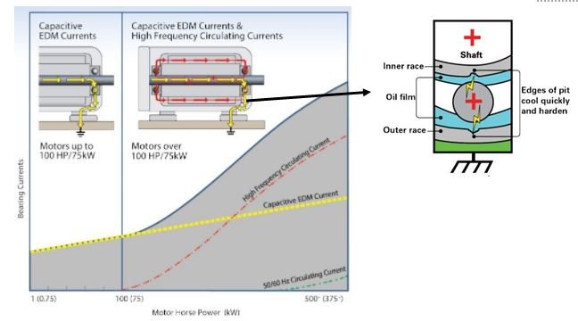
Current generation and bearing damage in electric motor [3]
Solutions
There are several different ways to prevent EDM damage. The electrical energy must be managed in most cases as the generation of stray electrical energy is unavoidable. Diverting the stray currents via a different path to ground and insulation of the bearings are two common methods of controlling electrical energy.
Traditional shaft grounding
Grounding devices create a path of least resistance for the stray electrical current diverting the electrical energy from sensitive components to the ground in a controlled and predictable manner. Grounding devices are good at controlling the capacitive current. These devices while effective have been known to wear over time. The spring-loaded carbon brushes commonly used in these grounding devices tend to wear creating dust which can cause problems due to contamination. [4][5] For this reason they have also been notorious for maintenance issues.
Bearing protection ring

AEGIS protection ring microfibers [6]
Bearing protection rings such as the one made by AEGIS are another type of grounding mechanism. These ring us conductive microfibers to channel electrical energy out of the shaft. These microfibers can number anywhere in the hundreds of thousands to millions enabling the ring to conduct large amounts of electrical energy. [3] The fibers are displayed in figure 4. These low friction rings require far less maintenance and boast a superior operating lifetime in comparison to traditional grounding methods.
Conductive lubrication
Instead of diverting the electrical energy from the bearing conductive lubrication has also been used to allow the current to pass though the bearing. Conductive lubrication prevents a large voltage buildup by easily allowing the current to flow out of the system. The insulating grease film in normal bearings prevents current from passing though until the voltage buildup is sufficient enough to arc through the insulating lubricant film. This arcing can cause heavy electrical damage. Conductive grease has proven to be useful, but while the grease prevents bearing damage from electricity it has its own downfalls such as shorter lifetime and increased wear. [5]
Insulated coated bearings

Bearing with insulated outer ring

Bearing with insulated inner ring
Coatings such as aluminum oxide will also block electrical current in the same way as ceramic bearings. When properly implemented coated bearings have been successful at preventing electrical damage. The coating can be applied to the inner or outer ring of the bearings. Large bore diameter shafts recommend coating the inner ring while small diameters usually recommend coating the outer. Coatings have been known to wear or chip from improper installation or usage resulting in loss of electrical insulation. Condensation can also affect the coatings effectiveness, so many coated bearings are also sealed to prevent the ingestion of moisture. It should be noted that electrical insulation prevents bearing damage but does not prevent the generation of electrical energy in the shaft via coupling. This energy will still look for the path of least resistance to ground.
Ceramic hybrid bearings

Hybrid ceramic bearing (silicon nitride)
Insulation methods such as using ceramic ball bearings and coatings have become common. The ceramics block the circulating electrical current from traveling through the bearings therefore preventing the bearing from taking EDM damage. Ceramic bearings have also been known to reduce the operating temperature of the bearing, which extends the life of the lubrication used, and they also require less lubrication than traditional steel bearings. [7] Figure 7 shows a hybrid or ceramic bearing with silicon nitride ceramic balls, often used in wind applications.
Conclusions
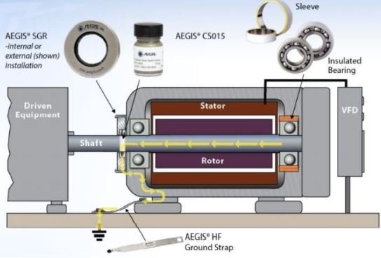
Typical current prevention layout
In practice providing a ground for stray electrical energy and protecting high risk bearings via insulators can save operators time and money. Using a grounding system alone provides a path for the stray capacitive electrical energy to make it to ground but depending on bearing position it could still take electrical damage via circulating currents. Ceramic bearings or insulated bearings with a grounding system installed best protects high risk bearings from electrical damage. Figure 8 displays a common configuration for motor/generator protection. Using the grounding ring along with an insulated or ceramic bearing in one or both positions best protects the system from both circulating and capacitive currents.
Resources
www.malloywind.com/generator-bearings
[1] M. Whittle, J. Trevelyan, and P. J. Tavner, “Bearing currents in wind turbine generators,” Journal of Renewable and Sustainable Energy, vol. 5, no. 5, p. 053128, 2013.
[2] “Influence of VFD on motor SHAFT voltage and bearing currents,” VFD. [Online]. Available: http://www.vfds.org/influence-of-vfd-on-motor-shaft-voltage-and-bearing-currents-984683.html. [Accessed: 30-Aug-2021].
[3] “Bearing Protection Best Practices,” Aegis.com, 2019. [Online]. Available: https://www.est-aegis.com/datasheets/presentations/AEGIS_BearingProtectionBestPracticesPresentation.pdf. [Accessed: 31-Aug-2021].
[4] “Preventing bearing Failure: Third time lucky at Oregon wind farm,” Renewable Energy World, 09-Sep-2019. [Online]. Available: https://www.renewableenergyworld.com/baseload/preventing-bearing-failure-third-time-lucky-at-oregon-wind-farm/#gref. [Accessed: 30-Aug-2021].
[5] “A better way to protect generator bearings,” Windpower Engineering & Development. [Online]. Available: https://www.windpowerengineering.com/a-better-way-to-protect-generator-bearings/. [Accessed: 31-Aug-2021].
[6] “Only AEGIS Shaft Grounding Rings Provide Both Contact and Noncontact Grounding,” aegis.com, 2016. [Online]. Available: https://www.est-aegis.com/datasheets/AEGIS_Contact_Noncontact_Technology.pdf. [Accessed: 31-Aug-2021].
[7] “XL hybrid bearings - protect your turbine from electric currents,” SKF. [Online]. Available: https://www.skf.com/us/industries/wind-energy/drivetrain/generator/skf-xl-hybrid-bearings. [Accessed: 31-Aug-2021].
[8] Malloy website for more information on insulated and ceramic bearings relevent to Wind applications. www.malloywind.com/generator-bearings
If you have any questions please give me a call at 605-357-1015
-Nathan Stang