
Blade Bearing Cracking Rings Part 2: Causes and solution
By Cory Mittleider on 10/12/21
Background
Cracking rings is the most dangerous form of failure on blade bearings. If operated this way for too long the blade can fall from the tower risking additional damage to the tower, property damage and worst of all personal injury.
In part 1 of the ring cracking article here we showed external pictures of ring cracking found in the field. In this second part we will show what the cracks look like inside, the causes of these cracks and importantly how to solve them.
Fig. 1: Blade bearing with crack in outer ring near lifting plate
Cracking rings as a failure mode is not new, but some of the newer platforms are having these failures much earlier and at a much higher rate than ever before. We have spent a great deal of time investigating this new generation of cracking failures both from teardowns and review of the application.
Cross-section of cracked ring
When the cracked surface is exposed many progression lines, also known as beach marks are observed. This indicates the failure started and stopped many times as it worked its way through the entire cross-section of the ring. These progression lines are clearly seen initiating at one point and radiating outward just like a pebble thrown into a lake. These lines are typical of a fatigue related failure with cyclical loading as described below. Figure 2 shows the entire cross-section of a cracked ring and an enlarged region showing the initiation point and beach marks.

Fig. 2: Visible beach marks radiating from the initiation point
Understanding the application
The cracking ring failures are all very similar in appearance. With additional background of the bearing design and application loading it becomes easy to see the major contributors to this problem.
High hoop stress
The largest contributor to forces that would cause a bearing to crack is hoop stress. In the application of a wind turbine these hoop stresses are created by a combination of application and bearing design. Hoop stress on the outer ring of the bearing leads to a peak stress concentration inside of the bolt hole just below the blade side raceway. This leads to a similar appearance of the cracked ring face independent of bearing brand and turbine model.
The loads applied to blade bearings are high and are growing tremendously with longer blades. Additionally, the internal design of the blade bearings is such that hoop stress is inherent with the applied loads. The combination of internal design and ever-growing applied loads is really pushing the limits of this bearing type.
Bending moment
Blade bearings are subjected to multiple load types; axial, radial, and moment loads as shown in figure 3. Additionally, the loading scenario for a blade bearing is quite complex as the entire bearing is moving around the main shaft axis at the same time as it is required to allow for pitching of the blades. In this application approximately 90% of the load applied to the rolling elements / raceways is from resulting bending moment loads.
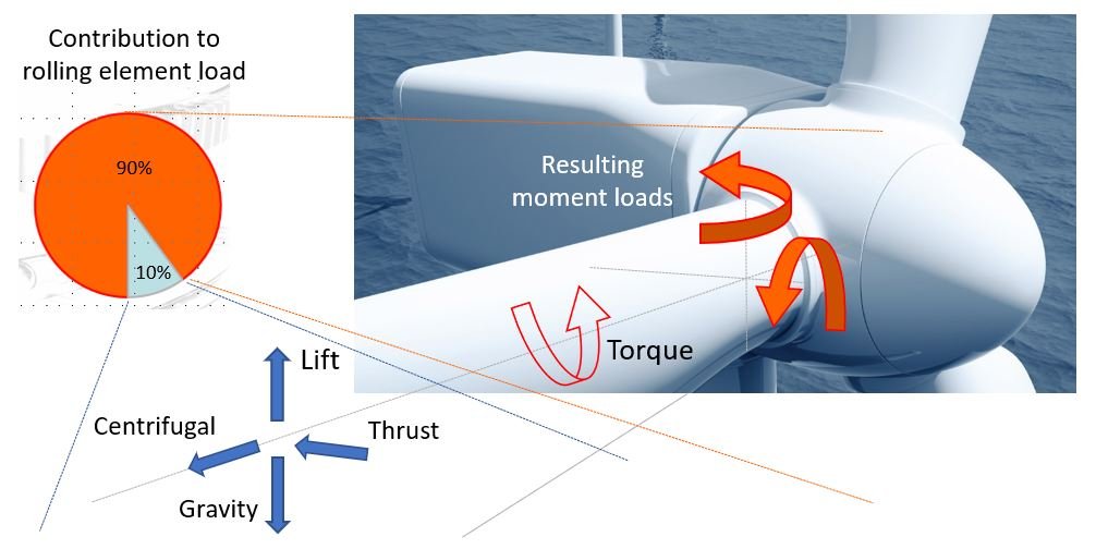
Fig. 3: Applied loading that contributes to rolling element load
Moment load is defined by the force applied multiplied by the distance at which it is applied. With increasing blade lengths on new wind turbine platforms both factors increase which leads to a compounding increase in bending moment load applied to the bearing as shown in figure 4.

Fig. 4: Effect of increasing blade length on moment loads
Internal design - 45° contact angle
The internal design of blade bearings used in this application includes 2 rows of balls preloaded at a 45° contact angle. The way that this bearing carries the applied load results in resolution of these forces into axial and radial components as seen in figure 5. The axial components transmit the load from the blade directly to the hub which is desirable.
The radial components, however, lead to negative effects such as ring separation, ring ovalization, and changing contact angle. This leads to a dramatic increase in hoop stress in the outer ring. The larger the bending moment applied, the larger this hoop stress becomes.
This also means that the contact angle of the balls on the raceway changes depending on the applied load. This contributes to other detrimental effects as discussed in the cage failure article here.
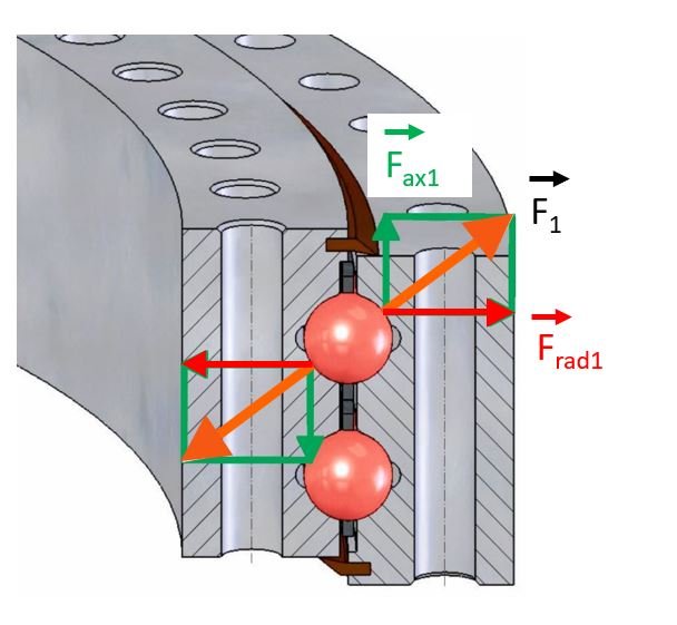
Fig. 5: Resolution of forces for bending moment applied to 2-row 4-point bearing type
Additional factors
Blade bearings are very carefully designed and evaluated against predicted loads to ensure proper life and operation during turbine life. When evaluating failures due to cracking rings there are usually some additional real-world factors that compromise the bearing system and act as the initiator. Sometimes these come from the bearing itself and other times from the application. Below are some examples of what could lead to bearing cracking.
Corrosion pitting
In the early years of wind turbines there was no specification to protect the inside of the bolt holes on blade bearings. In cases of extended transportation or storage times corrosion could start inside of these bolt holes. After some time, it was discovered that even these very small corrosion pits developed in the bolt holes was enough of a compromise in the integrity of the bearing that the crack started to form and after many cycles the crack propagated though the entire ring cross-section. Figure 5 shows corrosion in outer ring bolt holes. Figure 6 shows a close-up image of a crack initiated from a very small corrosion pit.
As described above the highest concentration of stress in the outer ring of the bearing is inside of this same bolt hole just below the blade side raceway. If there is a corrosion pit near this high stress area the pit creates a concentration that will initiate a crack.

Fig. 6: Very small corrosion pit initiation point
Surface roughness
There have also been cases where the surface roughness of the bore holes has been identified as the initiator. This is like the corrosion pitting in that it is a compromise of the integrity of the bolt hole that causes a stress concentration and initiates the crack.
Thread marks
Even if the bolt hole has a great corrosion protection system and the machined holes are all acceptable in roughness the bolt hole still has the possibility to be compromised at installation or during operation. When installing bearings and trying to align perfectly 60 or more studs with the bolt holes in the bearing it is quite easy to drag the stud threads in the bolt holes potentially damaging the corrosion protection or even marring the smooth surface of the bolt holes.
It is common to see marks from threads inside of bolt holes from rubbing during operation, as shown in figure 7. This rubbing first wears off the corrosion protection but then proceeds to rub grooves into the bolt hole. This action opens the opportunity for corrosion initiation or stress concentration at the thread groove directly initiating the crack.

Fig. 7: Rubbing marks of threads inside of bolt holes
Cross-section weakness
Slewing bearings of the 2-row 4-point type use a filling slot for loading of the balls into the bearing during construction. The cross-section of this area is shown in figure 8. These filling slots are plugged, and plugs are pinned in place, but this part of the bearing has a reduced cross-section of core material making it a known weak point. The filling plug location is very carefully located on the turbine to be in the lowest loaded area for this reason. In the application of a Wind pitch bearing there is no such thing as a no-load area, however. Since this area is already a known weak point any additional compromises in this area such as higher than predicted loading or defects in material or bolt holes will quickly lead to crack initiation.

Fig. 8: Filling slots cross-section
Hardening profile
The raceways of these bearings are induction hardened. This hardened layer is what provides long life against rolling contact fatigue, but this process must be carefully controlled and monitored with quality checks during production. This hardened layer of material has different characteristics than the rest of the tough core material. Figure 9 shows a cracked cross-section with the induction hardened layer visible. The distance between the raceway grease groove and the bolt hole is quite small. Although it did not cause the crack shown in the image, it is easy to see that maintaining control of this hardening depth is critical to avoid stress concentration in the bolt hole.
Fig. 9: Cross-section of cracked bearing showing the hardening depth
Stiffness joint
Some turbines have large heavy lifting or stiffening plates installed on the blade bearings. These thick plates add stiffness to a portion of the bearing, but at the end of the plate the stiffness abruptly changes creating a joint. In cases where the rings are highly loaded and deforming this stiffness joint becomes susceptible to a crack as seen in figure 10.

Fig. 10: Crack next to lifting plate
System deformation
The bearing type used in this application does require a certain amount of stiffness of the hub and blade root. If this support is inadequate the bearing will deform more than intended and this deformation will exaggerate the affects from the applied loading. This deformation is also known to contribute to cage failures as presented here. Figure 11 shows an amplified view of the deformation of a blade bearing during operation.

Fig. 11: Deformation of blade bearing in operation
Understanding the problem
Ring cracks are not initiated by a sudden impact or one time loading, they are a result of fatigue. This fatigue failure of blade bearings is a combination the applied loads, the bearing type selected, any of the additional factors mentioned above and, ultimately the number of cycles it is subjected to.
Cyclical loading
The pitch application is especially demanding for bearings. For every revolution of the main shaft the blade bearing is flipped over twice; once as it goes through the 12 o'clock position, and again through the 6 o'clock position. Each time the bearing passes through this vertical plane the direction of the gravity portion of the bending moment alternates direction as shown in figure 12. On a turbine that turns 12rpm 24 hours per day that adds up to over 12 million changes per year!

Fig. 12: Cyclical loading of blade bearings
Fatigue failures are a combination of the applied load, strength of material and number of cycles. The additional factors listed above describe ways that the application installed and operating in real life may deviate from idealized design conditions. Most of these are ways that the bearing itself could be compromised weakening it, but it is also possible that the loads were higher than estimated. If the loads were higher than estimated this could lead to cracking from fatigue even without the need for one of these other compromising factors.
Operational load
The operational load on the bearing comes not just from the applied wind load, but also from any induced loads from bending moments of the blades and structural deformations of the hub and blade root. The operational loads cannot be changed, and in order to solve the ring cracking problem the proposed bearing must fit within the same envelope, be capable to carry the applied loads, withstand the deformations found on the platform, and sustain all of this with the very high number of cycles.
Solving the problem
With a good understanding of the failure mode, bearing loads, and application we can begin to evaluate options to solve the problem.
Constraints
To upgrade failing blade bearings on installed turbines there are several constraints.
Turbine structure cannot be substantially changed. Any attempt to increase the stiffness of the structure will impact the mass balance of the turbine and may result in drivetrain issues.
Applied loads cannot be changed. Any attempt to downrate will affect profitability of the site.
Replacement bearings must fit in the same envelope and use the existing pitch system.
Replacement bearings should address the identified root cause of failure both from the cracking discussed in this article and others such as the cage failure discussed in other articles.
Replacement bearings should not introduce additional failure modes.
Multiple options were evaluated to address the problems described above.
Bolt holes
Since the bolt hole in the outer ring is where the stress is concentrated it is clear that these should be improved upon. Bolt holes must be carefully machined to remain within the prescribed surface roughness range. Also bolt holes need to be corrosion protected to avoid corrosion pits forming within them.
For the applications that are having failures very early in their life however these measures are not enough. Even if the holes are manufactured perfectly and thoroughly corrosion protected there is still opportunity to damage the holes during installation or thread rubbing as described above. Also, we are seeing indication that some of these applications may fail from fatigue alone without additional defects within the hole.
Bearing design
When the bending moment from the blade is applied to the bearing the 45° contact angle inside of the bearing induces a large amount of radial force leading to excess hoop stress. This is a substantial contributor to the total hoop stress in the outer ring leading to fatigue cracking. Any attempt to modify the existing 45° contact angle bearing will not change this load contribution. Additionally, the 2-row 4-point contact design will always need the filling slots in one ring leaving one area with a reduced cross-section. Figure 13 shows the force resolution for an applied moment load to this bearing type.
Fig. 13: 2-row 4-point force diagram
If you cannot avoid the detrimental deformation effects, choose a bearing design which can simply withstand it!
The most robust solution for this problem is offered by the T-Solid bearing design. The T-Solid bearing design has 3 raceways which distinctly separate the way that the load is carried within the bearing. The small radial loads are carried by the cylindrical rollers on the 0° contact angle. The very large bending moment loads are carried by the 2 ball raceways at 90° contact angle. This 90° contact angle is a critical part of this solution to connect the moment loads directly to the hub axially rather than inducing the large radial component caused by the 45° contact angle. This different internal design reduces hoop stress in the outer ring by over 30% creating a very large service factor against cracking. Figure 14 shows how this T-Solid design carries loads with its 3 rows. This T-Solid design also addresses the root cause of cage failure mentioned in this article.

Fig. 14: T-Solid force diagram
Caution
There is another type of bearing that looks similar to T-Solid called 3-row roller (3RR). This bearing type also has 1 radial row with 0° contact and 2 with 90° contact angle. The major difference is that this bearing type requires an even stiffer structure than the original 2-row 4-point type does. So, if lack of system stiffness is a contributing factor to failures of blade bearings, this type should not be used. Without sufficient system stiffness the 3RR type will edge load the rollers accelerating wear as indicated in figure 15. The fatigue life of this bearing type can be even shorter than the 2-row 4-point bearing type.
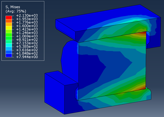
Fig. 15: Edge loading of 3RR bearing if structure is not sufficiently stiff
Next steps
The first thing to do after finding a cracked blade bearing is to take the turbine offline eliminating the risks described above.
Replacement
The next step is scheduling replacement, but it is important not to simply reinstall the same part and expect a different result. Understanding the root cause of failure and selecting an upgraded bearing that is targeted at solving that root cause is critical to long term confidence that you will not need to revisit the same turbine again.
For replacement bearings please contact Malloy. We have already investigated the root cause of these failures on multiple platforms and integrated solutions to them in the blade bearings we stock. If the failure is from a turbine model we have not already investigated, we would like to work with you to identify the root cause and apply the appropriate countermeasures.
Articles about other blade bearing failure modes can be found below:
Cage failure --> **READ HERE**
Ring cracking Part 1 --> **READ HERE**
Raceway edge wear and fracture
False brinelling
For more information on this topic or to discuss failing bearings in your fleet please contact me at 605-357-1076 or email atcmittleider@malloyelectric.com
-Cory Mittleider