
Blade Bearing Basics
By Cory Mittleider on 6/30/20
Application
Blade bearings a.k.a. pitch bearings connect the blade root to the rotor hub. The blade bearings allow the blade position to be optimized at different stages of operation. This includes optimized angle of attack to control drivetrain load usually to maximize output, but the pitch system is also used as the emergency brakes to stop the system in case of failures. Properly functioning pitch bearings are critical to maximize productivity of WTGs.
Construction
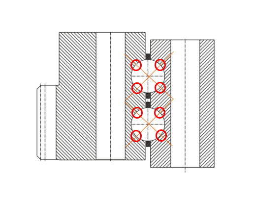
There are many different designs of slewing bearings available, each with their own advantages and disadvantages. In the early days of Wind the 4-point contact ball bearing was selected, and today the 2-row 4-point contact bearing accounts for approximately 99% of Wind Turbine blade bearings.
This bearing uses a gothic arch raceway curve as seen in figure 1. The design of this curve allows the manufacturer to control the contact and operational characteristics of these bearings. These bearings are designed and built with a 45° contact angle as shown in figure 2. This creates the 4 points of contact that the bearing is named for.
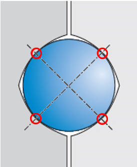
During assembly of this bearing, ball sizes are carefully chosen to micron finishes (.001mm) to meet the design requirements of the application including specific preload and break away torque.

Fig. 3: Components of a blade bearing
Application
The application of Wind turbine pitch bearing is quite demanding. The bearing must carry radial loads and axial loads, as well as bending moments on 2 different planes. Figure 4 gives an approximate breakdown of forces contributing to rolling element loads. Only 10% of the load is from direct forces like thrust and gravity, while 90% comes from the resulting bending moment of these forces acting on the blades.
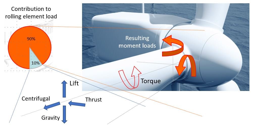
Fig. 4: Contribution to rolling element load
Further inspection of these load conditions reveals there are 2 moment load cases:
Gravity Moment Load:
Smaller force
High frequency of occurrence
Alternating direction on every revolution

Fig. 5: Gravity loading on blade bearing
Aero Moment Load:
High force
Non-reversing
Swelling in magnitude (low to high force)

Fig. 6: Aero loading on blade bearing
The moment loads applied to the bearing are directly related to the magnitude of the force and the distance at which it is applied.
M =F x D
Moment formula
In pursuit of ever higher output turbine manufacturers are consistently increasing rotor diameter. For example, in 2019 the average installed rotor diameter was 121 meters, an increase of 44% over the average rotor diameter of 84 meters installed in 2010. When the blade length increases the weight of the blade and aerodynamic thrust forces increase, and both of these forces are applied at increased distances from the bearing leading to a dramatic increase in moment load. At the same time, manufacturers are attempting to maintain small blade root and bearing diameters to avoid logistics complications. Blade bearings as they are designed today are being pushed to their limits and exposing the weaknesses of the standard 2 row, 4pt contact design.

Fig. 7: Effect of increasing blade length on moment
Function
When the moment load of the blade is applied to the bearing it is supported by 2 of the 4 points of contact in each raceway (figure 8).
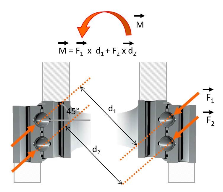
Fig. 8: Blade bearing with moment load applied
The nature of the 45° contact angle means these forces will be resolved to axial and radial components. This resolution of forces is shown in figure 9. The axial force component is shown in green because this is the component that transmits the applied load to the hub which is the desired load path. The radial component is shown in red; this component is not desirable as it pushes the rings apart leading to ovalization, hoop stress, and change in raceway contact angle.
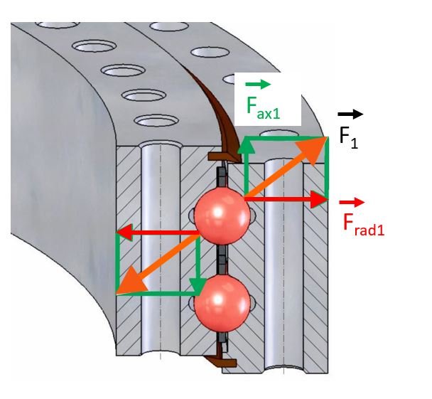
Fig. 9: Resolution of forces applied at 45° contact angle
Figures 10 & 11 show the hoop stress and change in contact angle experienced under high loads.


The combination of drastically increasing loads, the 45° contact angle bearing type, and other system inadequacies is leading to failures on multiple platforms. Some of these failures are occurring in as little as 2 years!
I will elaborate on these failure modes in following articles:
Cage failure --> **READ HERE**
Ring cracking Part 1 --> **READ HERE**
Ring cracking Part 2 --> **READ HERE**
Raceway edge wear and fracture
False brinelling
If you have any questions please give me a call at 605-357-1076
-Cory Mittleider